Plumbing and Sanitary work Methodology
Plumbing and sanitary quality and work methodology consists of three parts.
They are administration, installation and documentation.
1. ADMINISTRATION
a) Drawings
Upon award of an agreement along with receipt of all architectural, plumbing and structural drawings related to plumbing installations, prepare a schedule of drawings shall contain following minimal information:
1. Drawing number
2. Title of the drawing.
3. Name of the project.
4. Names of Client, Architect, Consultant(s), Contractor.
5. Date of submission.
6. Scale.
7. Revision number and revision note with dates
8. A note whether the drawing is approved or pending approval.
9. General notes, if any.
10. Specification notes, if any.
This kind of schedule is made to keep track of sketches required and monitor the status including submission, revision and approval. It may be modified and updated periodically when fresh architectural drawings are issued.
b) Construction Schedule
A construction schedule shall be prepared based on the target dates provided by the client/consultant. All initiatives shall be made to stick to this schedule. It will be analysed weekly and revised if any delays occur scheduled to unforeseen and inevitable circumstances, keeping in mind the final date of completion.
c) Materials
A 'Material Proposals' schedule will be submitted to the client/ Consultant giving details of materials, manufacturer's name, technical details etc. Once these are approved, purchase will get started and a "Material procurement schedule" will be submitted.
Total attention shall be taken to guarantee that the materials that finally arrive at site meet all requirements of technical specifications and the bill of quantities, for which the store-keeper and site specialist ought to be responsible.
d) Workmen
Sufficient workforce might be implemented always to meet the approved construction schedule. The workforce will be suitably optimized as demanded by genuine site conditions.
e) Project Management
Workers of the site can be organised as according to the project organisation Chart issued at the beginning of the project. Any amendments to the chart may be duly recorded and suggested to the project managers. Weekly site meetings will be attended via a senior member of the contractor’s crew. There ought to be an occasional visit via the Executive Management.
Any deviation from approved operating drawings made by way of site commands through the client / consultant will be indicated within the ‘As installed’ drawings to be issued on the cease of the project. These instructions will ought to be officially confirmed before the specified changes or deviations are applied. Time or value implications will be delivered to the client’s notice finally. The site engineers shall co-ordinate with agencies for handling other services like electrical, HVAC, Interiors etc, the site engineers shall co-ordinate with agencies when required. A strict quality control programme should be implemented, and all efforts must be made to achieve and maintain a high degree of workmanship.
f) Safety Plan
A safety plan or wellbeing design shall also be submitted prior to beginning of the work. Due care will be taken about all the protection elements of the works. Relevant PPE (non-public protective device) shall be utilized by all employees working at the installation.
2. INSTALLATION
Given below are method statements for general plumbing installations.
a) Excavation of trenches
1. Check design of the pipeline and get endorsement from the Client's representative. Barricade sides of trenches to be exhumed.
2. Begin excavation works (Using manual work or an excavator machine). Guarantee that the width does not surpass the most extreme indicated.
3. Utilize a levelling instrument to make depth markings up and down the length of the excavation. In specific circumstances, it may not be down to earth to utilize a levelling instrument in a pipes or sewerage installation. In such cases, a tube level could be utilized.
4. Take into consideration more profound excavations to suit the PCC base of review chambers and at collars/joint of channels.
5. Additional care should be exercised for excavations deeper than 1.5m, especially in loose soils. Arrangements should be made for shoring the sides of trenches.
6. Care ought to be taken that excess excavations area unit forever avoided. If doubtful, excavate less and dispose of the additional depth within the next stage. crammed in soil invariably settles taking the pipe with it, distressful alignments.
7. Ensure that excavated earth is always stored away from the edge of the trench.
b) External piping – Water supply
1. Mark pipe lines in ground line with operating drawing and supply barricading.
2. Excavate trenches to needed depths as per operating drawings.
3. Prepare base of trench for laying pipes, as per technical specifications.
4. Lay the pipes on the prepared base and support them at adequate intervals.
5. Test the pipes for leaks harassed within the presence of consumer’s representative and maintain a ‘test certificate’ punctually signed by the representatives of the client and contractor.
6. Coat the pipes with the specified anti-corrosive treatment (if metal pipes are used).
7. Provide encasement with sand/granular material, if specified.
8. Backfill trenches in layers including compaction.
c) External piping - Sewerage & Storm water
1. Mark pipe lines in ground according to working drawings.
2. Excavate trenches to needed depths as per operating drawings.
3. Prepare base for laying pipes.
4. Lay pipes according to specified gradient.
5. Perform pressure driven/smoke investigate and acquire accreditation frame from customer's illustrative.
6. Provide encasement with concrete / sand/ granular material, as specified.
7. Refill trenches in layers including compaction
d) Shaft Piping
1. Check for funnels on the plastered shaft dividers as indicated by points of interest in the working illustrations. Guarantee that the plastering is finished as it will be practically difficult to plaster dividers after the pipes are set up.
2. Fix brackets as per details shown on the working drawings. A clear gap of 25 to 50mm shall be maintained between pipe and wall surface.
3. Clamp pipe assemblies on to the brackets. ensure the pipes area unit in ‘line’ (horizontal runs) or in ‘plumb’ (vertical stacks). Wherever enlargement / contraction is a priority, make sure that pipes don't seem to be stiffly command to brackets.
4. Make cut-outs on the shaft walls for branch pipes at locations shown on the drawings.
5. Embed sleeves wherever required. Guarantee that annular space in sleeves isn't more than 25mm. Annular space should be loaded with yarn and adaptable sealant after establishment of pipe through the sleeve.
6. Provide branches on the pipe assembly for connections to internal pipe work. Provide uninflected valves on water system pipes at locations shown on operating drawings; at simply approachable heights.
7. Test the pipes for leaks under specified pressure for the specified duration.
8. Tests must be witnessed and approved by client’s representative.
9. Paint the pipes as per approved colour code and provide identification labels where called for.
10. Take measurement of pipes installed. A client representative must be present and should acknowledge the records.
11. Terminate soil, waste and vent pipes with vent cowls at such heights higher than terrace level. Make sure that vent cowls don't seem to be terminated among one meter (horizontally and vertically) from any window openings.
12. Terminate installation risers with automotive air vents (with analytic valves) and down pipes with drain plug/drain valve – all as per drawings. Make sure that installation pipe work would be self-venting and self-draining.
13. Connect the soil stack to inspection chamber at ground level.
14. Connect waste stacks to the gully trap at ground level. Connect the gully trap to the inspection chamber.
e) Pipes in wall chases
1. Ensure that walls are in any event harsh put and complete levels are set apart by the civil contractor. On the off chance that appropriate cladding levels are not denoted, the funnels could be too profound or excessively shallow inside. Pipes somewhere down in the wall will require utilization of augmentation areolas at fixtures. Divider ribs of hid stop cocks, disguised shower blender and so forth won't fit-in effectively.
2. Mark pipe lines on walls as shown on the working drawing.
3. Chase the walls to required depth using a chasing machine.
4. Assemble piping beginning from branch left in shaft and introduce in the wall pursue with braces. Utilize pre-created gatherings wherever conceivable.
5. Locate fixture outlets according to working drawing and tile-module drawings. Title modules shall be marked on walls by the civil contractor.
6. Plug all openings and test the pipe work for leaks under specified pressure and for required duration. Test should be witnessed and approved by authorized personnel.
7. If metal pipes are used, apply anti-corrosive coating or wrapping on the pipe. Make sure that the tested pipe joints are not disturbed.
8. Insulate hot water pipes with the specified material. Wherever possible, pipes may be pre-insulated/pre-wrapped, leaving joints, prior to installation in the wall chase.
9. Close the wall pursues with bond mortar. On the off chance that site conditions require a depth of more than 100mm to be pursued, it is prudent to utilize a reasonable work while putting and 'making great'.
f) Pipes in sunken floor or suspended in ceiling (Drainage)
1. Ensure that base water-proofing of toilet floors is completed.
2. Locate and mark positions of soil and waste outlets and make core drills where necessary.
3. Assemble pipe headers and connect them to branches left in the shaft for this purpose. Pre-fabricate wherever possible.
4. Ensure that pipes area unit in correct slope and area unit supported adequately. invariably make sure that the spacing of supports is as per specifications. make sure that floor traps area unit put in level (not tilted) so the water seal isn't diminished
5. Test the pipes and attend to leaks, if any.
6. Manage the filling of depressed floors by civil contractual worker with the goal that the arrangement and incline of waste funnels are not disturbed. It is in the pipes contractual worker's enthusiasm to guarantee that water sealing of the centre drills is done and tested.
7. Keep all open ends plugged to prevent ingress of construction debris.
g) Sanitary fixtures & CP fittings
1. Flush the installed pipe work for water supply and drainage to remove debris or blockages, if any.
2. Install hygienical fixtures, taps and toilet accessories. Use screws with nylon washers to repair vitreous crockery and PTPE tape for installation of taps to pipe work.
3. Check CP fittings for leaks and firmness and refit them if necessary. Ensure that proper tools are used, and they must not make scratches or any other kind of damages on the chrome plated fixtures.
4. Commission the toilets in the presence of the client’s engineer.
5. Handover the toilets formally using the forms provided for the purpose.
h) Disinfection
The water distribution system should be thoroughly disinfected before being use. The following simple procedures will make sure the satisfactory results:
1. Flush and clean water tank and distribution pipe work with potable water to remove dirt and any foreign matter.
2. Fill the tank with water mixed with chlorine solution at the rate of 50 parts per million. Retain chlorinated water in the system allowing the chlorine to spread throughout pipe work.
3. Open the farthest draw-off points or drain plug/valve to draw water. Repeat the procedure till odour of chlorine is felt at all locations when checked at random.
4. Drain out chlorinated water and fill the system with potable water.
3 DOCUMENTATION
a) As Installed Drawings
1. Mark adjustments made from the running drawings; if any. That information has been maintained on occasion at some stage in progress of work.
2. Get ready 'As-Installed' drawings. This is a basic requirement frequently disregarded. After the development group leaves the venture site, it is difficult to distinguish pipe routings and so forth without these drawings.
3. Hand them over to the client with specified number of hard and soft copies.
b) Operation & Maintenance Manuals
The O & M manuals should contain following minimum information:
1) A brief description about the project and the installations carried out.
2) Schedule of mechanical / electrical equipment and sanitary fixtures are installed.
3) Schedule of as-fitted drawings.
4) Manufacturer’s O & M manuals and any warrantees issued by manufacturers.
5) List of recommended spare parts.
6) Notes / recommendations on preventive and remedial maintenance works.
7) List of manufacturers with their local contact details.
8) Technical catalogues of important products used on the installations.
9) Reports / certificates of all tests conducted during progress of work and any commissioning reports.
c) Virtual Completion Certificate
On taking care of over the as-fitted drawings and O&M manuals, a joint site visit might be masterminded with the customer's representative to guarantee all works are finished agreeable to them and get a certificate to that degree.
Date of this certificate will be the begin date of Defects Liability Period.
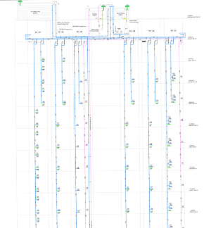
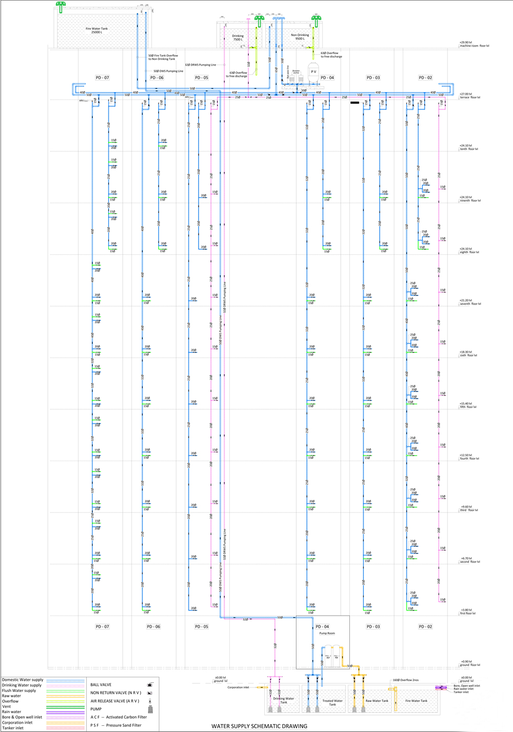
Water Supply Scheme Model
Water Supply Scheme Model
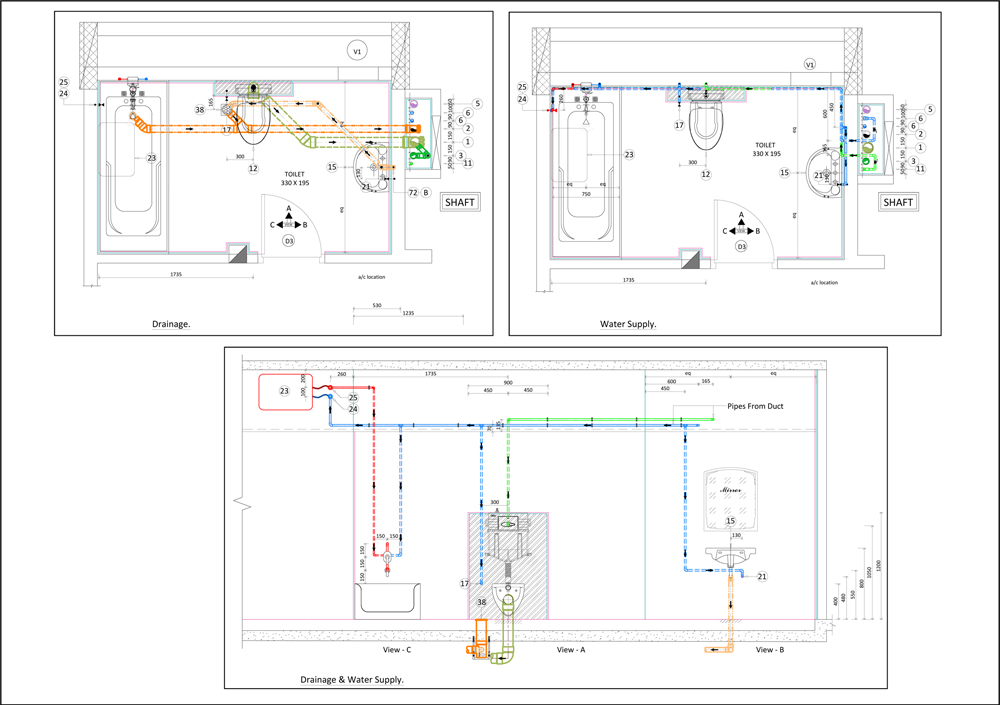
Typical Floor Internal Drainage & Water Supply Model
Typical Floor Internal Drainage & Water Supply Model